|

|

|

|

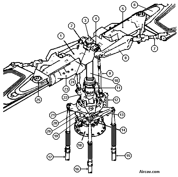
| 1. Main rotor hub yoke | 14. Swashplate support |
| 2. Trunnion | 15. Collective control hydraulic cylinder |
| 3. Mast nut | 16. Lateral cyclic control hydraulic cylinder |
| 4. Elastomeric bearing | 17. Fore and aft cyclic control hydraulic cylinder |
| 5. Grip | 18. Transmission |
| 6. Main rotor blade | 19. Drive link |
| 7. Drag brace | 20. Swashplate outer ring |
| 8. Pitch horn | 21. Swashplate inner ring |
| 9. Connecting tube (pitch link) | 22. Scissors and sleeve assembly |
| 10. Mast | 23. Sand deflector |
| 11. Friction collet | 24. Mast nut lock |
| 12. Antidrive link | 25. Main rotor blade retention bolt |
| 13. Collective lever | 26. Collective idler assembly |
|
|
|
|
| Updated: 12 January 2008 | Born on 01 January 1999 |